EQMod
Installation
The EQMod Mount driver is available for download as a 3rd party driver from INDI's download page. Under Ubuntu, you can install it via::
sudo apt-add-repository ppa:mutlaqja/ppa
sudo apt-get update && sudo apt-get install indi-eqmod
Features
This INDI EQMod Mount driver interacts with a mount controller using the Skywatcher Protocol through a serial link. It can directly drive SkyWatcher and similar mounts through a serial port (see EQDIRECT interface for more details), or any other mount hardware which uses this protocol. The EQMod Mount driver can also be used with the Synscan controller if PC Direct Mode is enabled in the handset. However, this approach can be problematic and generally not recommended. For wired connections, using EQDirect cable is recommeneded.
The INDI control panel exposes data associated with the device and permits parameters to be set. In normal operation, higher level software, such as EKOS, will control the mount, but this document will utilise the INDI control panel GUI to explain the available features.
Current features supported:
- Accurate gotos
- Multiple alignment point and alignment algorithm support
- Independent slew speeds for both axes variable between x0.05 to x800 of the sidereal rate (step x0.05)
- Sidereal, lunar, solar and custom trackrates
- Maintainance of pier-side
- Custom horizon limits
- Configurable custom parking positions
- Both pulse and ST4 guiding support
- Dome integration support
- PPEC mount support
- Joystick support
If you plan to use EQMod driver with AstroEQ, make sure to use the latest firmware v8.11+ as prior AstroEQ versions will fail to work with EQMod.
Connectivity
1. Cable (EQ Direct or USB)
To connect to the EQMod mount from a PC, Mac or a device like Raspberry PI, use a USB cable (if this is supported by the mount) or a EQDirect USB cable (such as those offered by Shoestring Astronomy).
Many vendors sell USB to RJ45/DB9 EQDirect-compatible cables and adapters. You connect the USB to your computer or embedded device running INDI and then use the driver to control the mount.
For direct USB connections to AZEQ5 or EQ6R Mounts, make sure to set the baud rate to 115200
2. Network
If EQMod is available over the network via an RS232-to-Ethernet adapter for example, use Ethernet connection mode and enter the corresponding IP address and port where the remote server is located.
3. Bluetooth
For bluetooth adapters, several adapters are avaiable from, for example, Shoestring Astronomy. When using Bluetooth adapter, it is highly recommended to remove modemmanager as it interfers with connection with EQMod driver. To remove it, use the following command:
sudo apt-get remove modemmanager
Then you can either use your OS built-in Bluetooth manager to pair with the EQMod Bluetooth adapeter, or you can permenantly bind it by adding the following line to your /etc/rc.local
rfcomm bind hci0 XX:XX:XX:XX:XX:XX 1 &
Replace XX:XX:XX:XX:XX:XX with your Bluetooth adapter MAC Address. To get the MAC address, use the hciconfig command to list bluetooth devices and their correspnding information.
Operation
Before starting the driver, make sure the mount is in the Park position and then power it up. The Park position can be set in the Site Management tab. By default, it is set to the Home position is which the telescope is pointing to the celestial pole with the weights down.
Then start the EQMod Mount driver. Once the driver is online, it will load the mount configuration.
First Time Use
When running the driver for the first time, go to the Connection tab and select the port to connect to. You can also try connecting directly and the driver will automatically scan the system for candidate ports. If EQMod is connected the network via a Serial-TCP (Ethernet or WiFi) adapter, then you can select Ethernet mode and enter the IP address and port for the adapter connected to the mount. After making changes in the Connections tab, go to Options tab and save the settings.
Main Control Tab
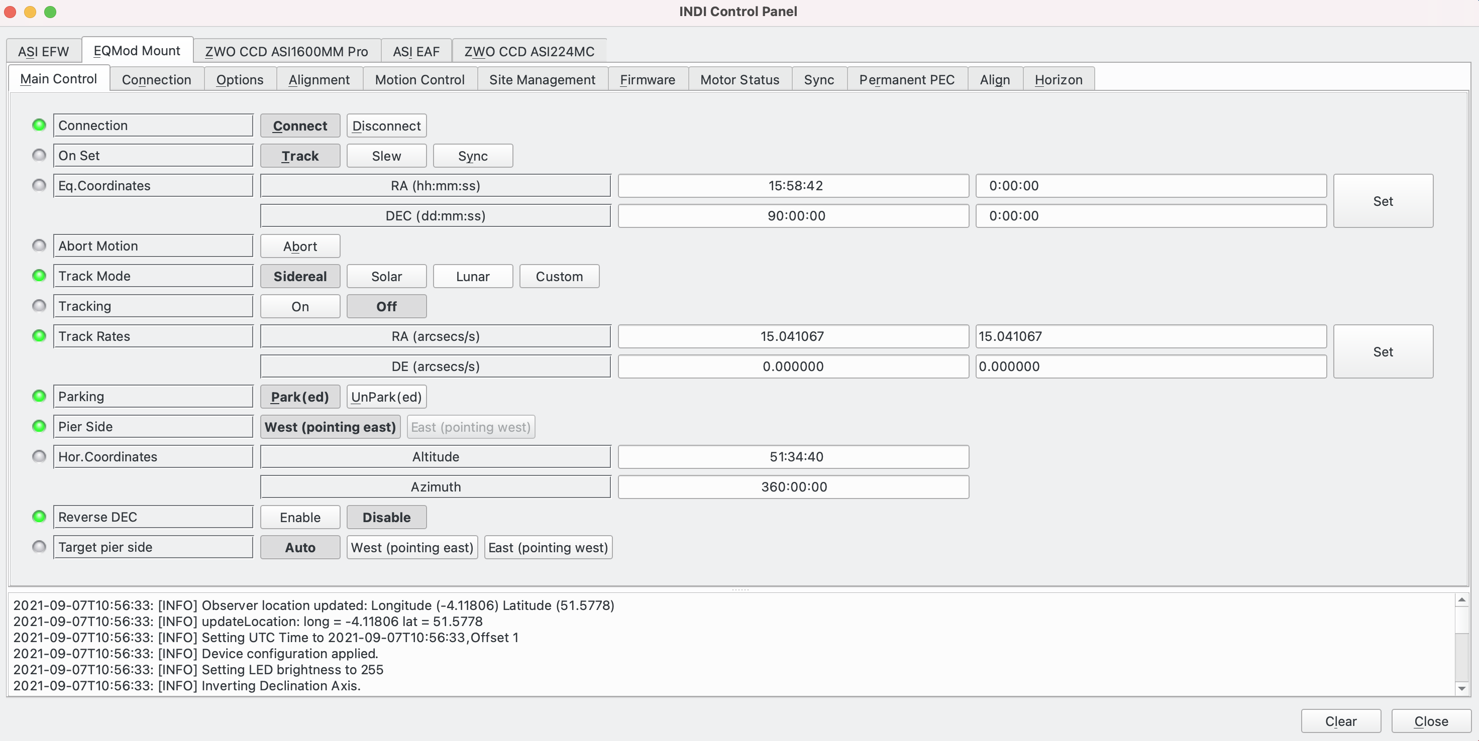
The Main Control tab is where the primary control of EQMod takes place. Users will seldom use this interface directly since most people will use powerful software such as Kstars/Ekos above the EQMod Mount driver to slew and sync the mount directly from the sky map without having to enter any coordinates manually. However, if necessary, control of the mount can be done from here:
- Connection: Displays and sets whether the driver is connected or not.
- On set: Describes the action to take when coordinates are set:
- Track: In this mode, when coordinates have been entered and set, the mount will slew to the coordinates entered and when it arrives there, it will engage tracking.
- Slew: In this mode, when coordinates have been set, the mount will slew to the new coordinates only.
- Sync: In this mode, when coordinates have been set, the mount will not move, but synchronise itself to the coordinates that have been entered. Note that the mount must be tracking in order for Sync to work.
- Eq Coordinates: The RA / Dec coordinates that the mount is currently pointing to.
- Abort Motion: Can be activated to stop the mount if it is slewing.
- Track Mode:
- Sidereal: This is used for DSO photography and often for Planetary photography. It compensates for the rotational spin movement of the Earth about its axis. This rotational movement is what makes objects appear to move across the sky. By compensating for it, from the perspective of the telescope (and camera) the object being viewed appears to be stationery and thus long exposures can be taken without star trails.
- Solar: This is used for Solar imaging. The mode combines Sidereal with the movement necessary to compensate for the Earth's rotation around the Sun.
- Lunar: This is used for Lunar imaging. The mode combines Sidereal with the movement necessary to compensate for the Moon's rotation around the Earth.
- Custom: Custom track rates can be defined in Track Rates.
- Tracking: Can be set On / Off.
- Track Rates: Displays the RA / Dec track rates associated with Track Mode. If Custom Track Mode is set, allows values to be set.
- Parking: Allows the mount to be parked or unparked:
- Parking: The mount slews to the Park position and Tracking is turned off. Once Parked, the mount cannot be moved, i.e. it cannot slew or track.
- Unparking: The mount position remains in the Park position, but it is now available to slew and track.
- Pier Side. Which side of the Meridian the mount is on (either East or West).
- Hor. Coordinates. This is a translation of Eq. Coordinates into the Alt / Az coordinate system.
- Reverse DEC. Reverse the Dec axis.
- Target Pier Side:
- Auto: The EQMod Mount driver calculates the pier side based on where the telescope is pointing and data in the Site Management tab. This is displayed in Pier Side. This is the recommended setting.
- West (pointing east): Force the mount to use the West side of the pier. Generally it is better to let the driver manage Pier Side and allow higher level software such as Ekos to perform a Meridian Flip as the telescope crosses the Meridian. However, there could be situations where, for example, an object is being viewed a short period of time before it crosses the Meridian and it is more efficient to start on the "wrong" side of the Meridian and continue viewing uninterrupted rather than use Auto, start observing and immediately have a Meridian Flip. Please note, however, that care needs to be taken to avoid the telescope hitting the mount if this option is selected.
- East (pointing west): Force the mount to use the East side of the pier.
Connection Tab
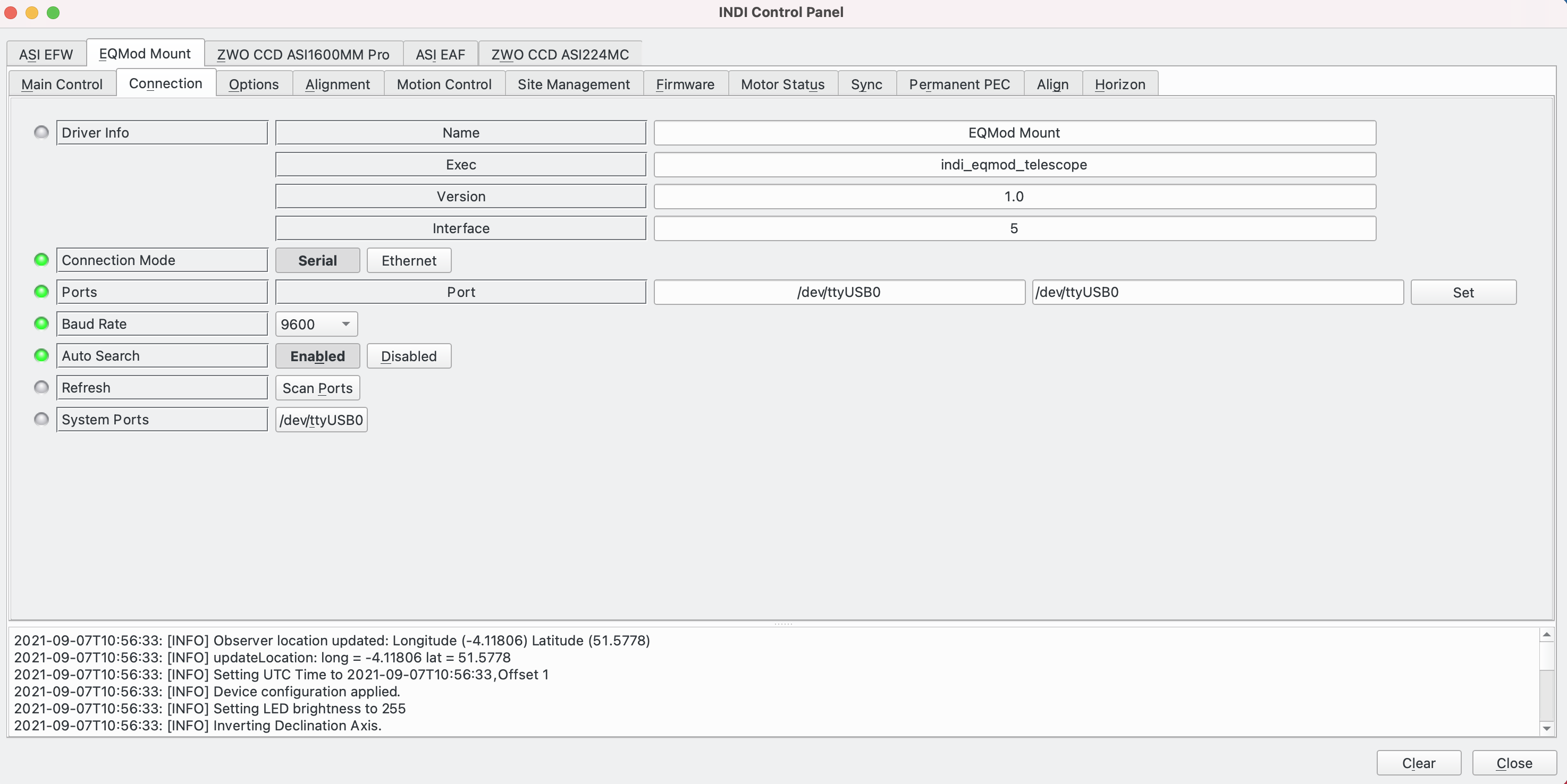
The Connection tab shows information related to the connection of the Eqmod Mount driver to the mount.
- Driver Info: Displays information about the driver.
- Connection Mode:
- Serial: Use this if connecting using USB either directly or through an EQDir cable.
- Ethernet: Uase this if connecting using ethernet.
- Ports: Displays the attached port and allows it to be changed.
- Baud Rate: The baud rate of the connection. Use 9,600 with an EQDir cable and 115,200 for a direct USB connection.
- Auto Search: If enabled, the driver automatically scans the system for candidate ports on startup or when Refresh is activated.
- Refresh: If Auto Search is enabled, when Scan Ports is pressed, the system scans for candidate ports.
- System Ports: The list of candidate ports to connect to.
Options Tab
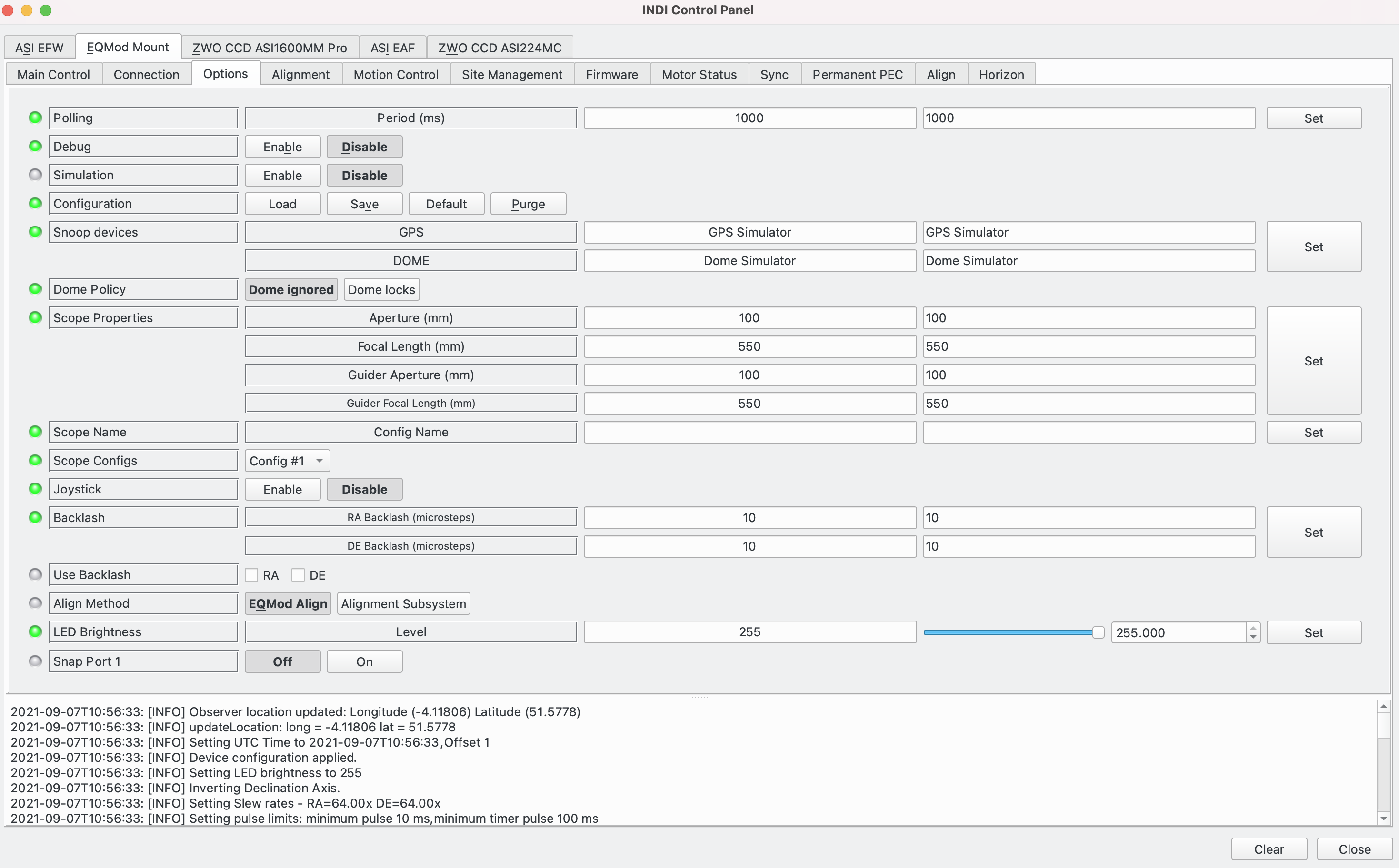
The Options tab, allows configuration of many parameters before and after you connect to the mount.
- Polling: Displays the mount polling period in milliseconds.
- Debug: Displays the debug status. Note that debug options are set in Ekos as described here.
- Simulation: Enable / disable simulation mode for testing purposes. In Simulation mode, parameters can be changed but not sent to the device.
- Configuration: Manage the driver configuration.
- Load: Load the last saved settings.
- Save: Save the driver settings.
- Default: Restore default settings that were shipped with the driver.
- Purge: Delete the configuration file.
- Snoop Devices: The driver supports the ability to listen to, or snoop on, parameters of other drivers.
- GPS: If using a GPS driver (e.g. INDI GPSD) then enter its name here. EQMod will sync its time and location settings from the GPS driver.
- Dome: If using a Dome driver, put its name here so that Dome Parking Policy can be applied.
- Dome Policy: If a dome is used in conjunction with the mount, a policy can be set if parking the mount or dome can interfere with each other. For example, you might want to always park the mount before parking the dome, or vice versa.
- Dome ignored: Take no action when dome parks or unparks.
- Dome locks: Prevent the mount from unparking when dome is parked.
- Scope Properties: Enter the scope details for the primary scope and, if appropriate, the guide scope. If using an Off Axis Guider (OAG) repeat the primary scope details for the guide scope. Up to six different configurations for Primary and Guider scopes can be saved separately, each with an optional unique label of Scope Name.
- Scope Name: Optional name of scope. Useful if you use several setups; be they different scopes or different setups on a single scope, e.g. with / without a focal reducer.
- Scope Config: Select the active scope configuration.
- Joystick: Enable or Disable joystick support. An INDI Joystick driver must be running for this function to work. For more details, check the INDI Telescope Joystick tutorial.
- Backlash: Set RA & DEC backlash in microsteps.
- Use Backlash: Control whether or not Backlash is used for RA and / or Dec.
- Align Method: Set the alignment method to use, either EQMod Align or Alignment Subsystem.
- LED Brightness. Set the level of brightness of the Polar Alignment LED on the scope.
- Snap Port 1. The Snap port is a mechanism to control the shutter on a DSLR camera through the mount. Activate it here.
Alignment Tab
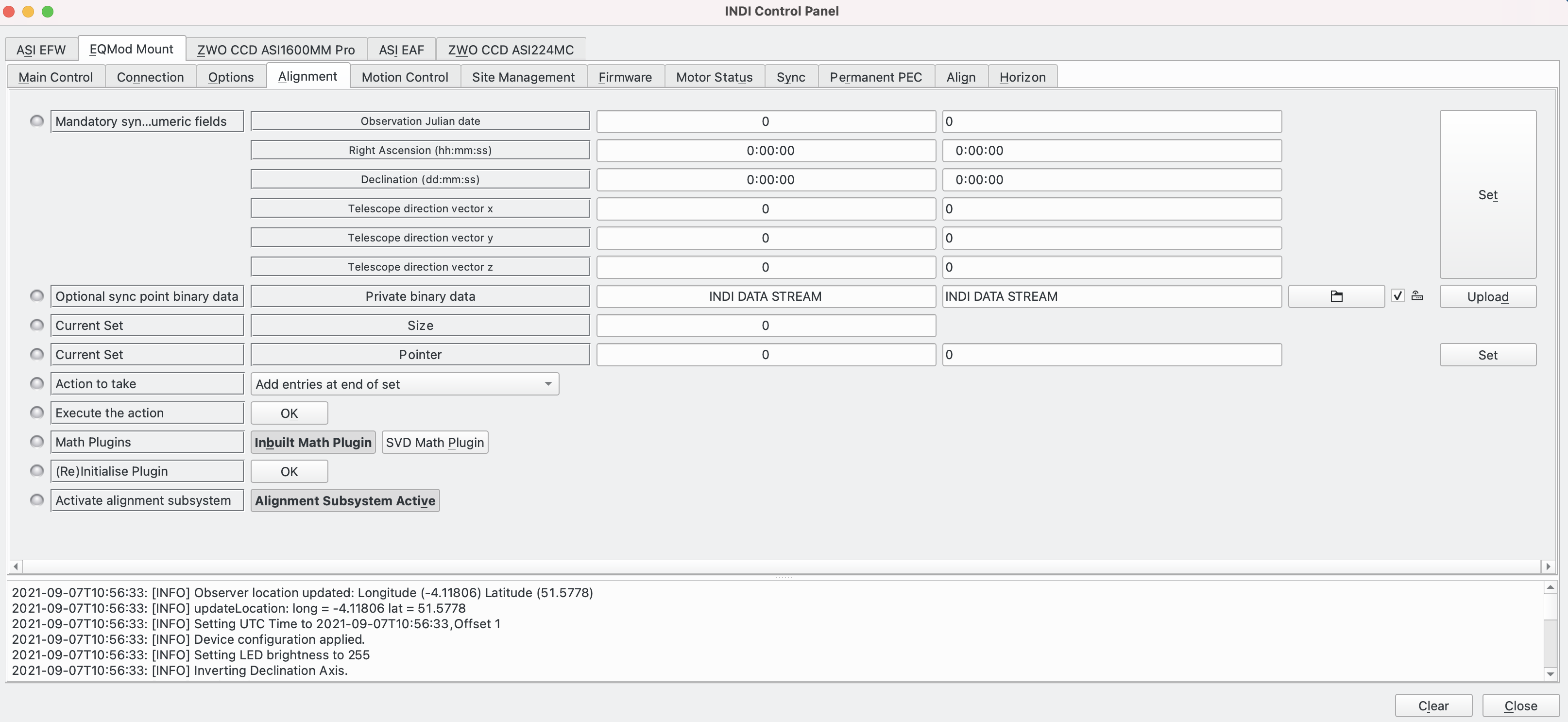
The Alignment tab displays information about alignment points. As this repeats data on the Align tab, please see the Align tab section for more details.
Motion Control Tab
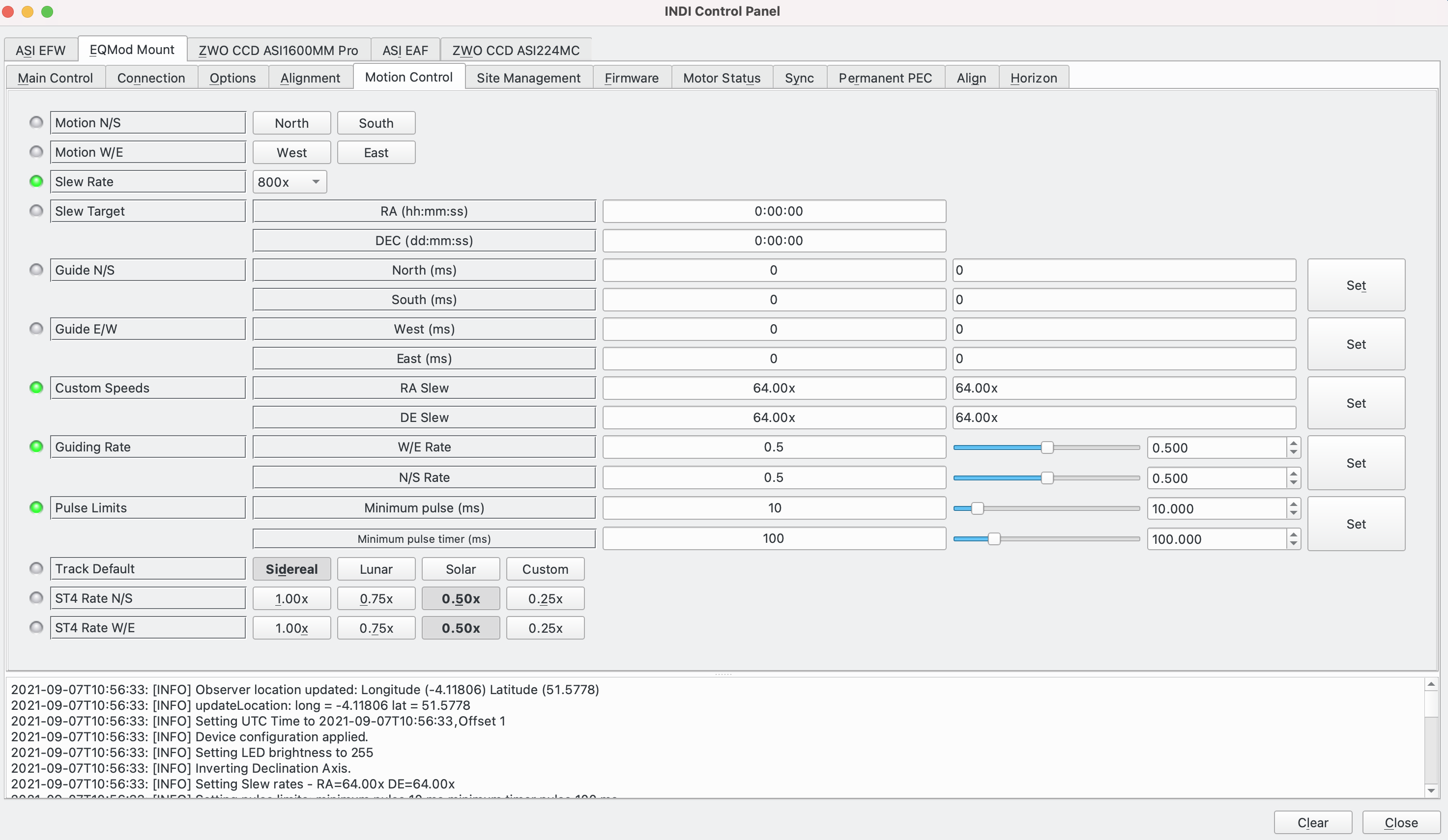
The Motion Control tab allows motion control parameters to be displayed and set:
- Motion N/S/W/E: Directional manual motion control. Press the button to start the movement and release the button to stop.
- Slew Rate: Rate of manual motion control above where 1x equals one sidereal rate. A range of options are offered. If Custom is selected, slew rates can be entered in Custom Speeds.
- Slew Target: The RA / Dec coordinates of a requested slew.
- Guide N/S/W/E: Guiding pulses durations in milliseconds. This property would normally be used by a guider application (e.g. PHD2) and not used directly.
- Custom Speeds: Customs speeds in RA & DEC axis when slewing.
- Guiding Rate: Guiding Rate for RA & DE in units of sidereal motion. For exmple, at 0.3x, the mount moves 0.3*15.04 = 4.5 arcsecond per second. So a guide pulse for 1 second (or 1000ms) would move 4.5 arcseconds.
- Pulse Limits:
- Minimum Pulse. ** guessing this is the ST4 equivalent of Minimum Pulse Timer?
- Minimum Pulse Timer. This is for pulse (as opposed to ST4) guiding. Only send the guide pulse to the mount if it exceeds the minimum value. Usually a value is set to stop the mount oscillating with continual small values that results in "chasing the seeing" without any guiding benefit.
- Track Default: Default tracking rate to be used on startup. See Track Mode on the Main Control tab for more details.
- ST4 N/S/W/E: The guide rate to use in units of sidereal motion for ST4 guiding.
Site Management Tab
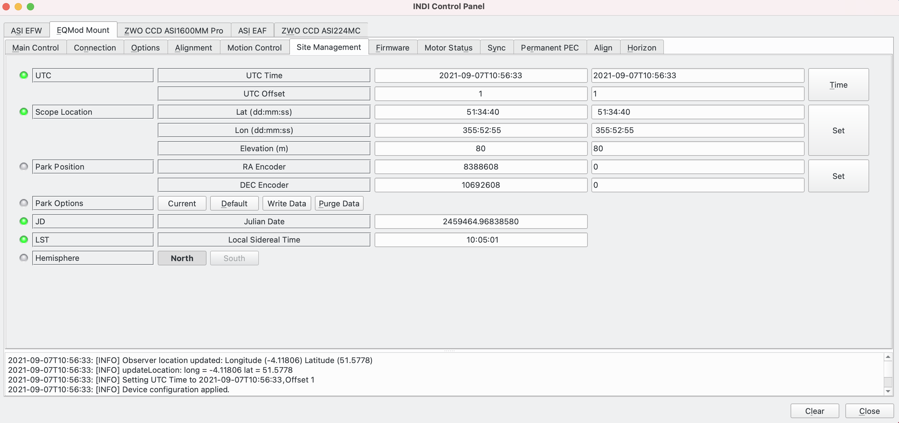
The Site Management tab displays and sets information about the telescope's location.
- UTC: UTC time and offset must be set correctly. The UTC offset is in hours.
- Scope Location: Latitude, Longitude and elevation above sea level must be set correctly. The longitude range is 0 to 360 degrees increasing eastward from Greenwich.
- Park Position: Upon connection to the mount, Ekos loads these values into the mount's motor controller to initialize the (stepper) motor step values. The default values represent the Home position of the mount.
- Park Options:
- Current: Set the parking position of the mount to current position.
- Write Data: This saves the current park position.
- Default: Sets the Park position to the Home position.
- Purge Data: Removes the current Park position data.
- JD: The current Julian Datetime calculated from UTC.
- LST: The current Local Sidereal Time calculated from UTC.
- Hemisphere: North or South. Which hemisphere the mount is located in, calculated from Scope Location.
IMPORTANT: It is important to understand the difference between the Home position and the Park position:
- Home position. This is where the mount (telescope) is pointed at the celestial pole (either North or South depending on which hemisphere the mount is located in) with the counter weights down (below the telescope). There is just one Home position. There are online resources that describe how to set this up.
- Park position. The Park position is user defined and can be anywhere. By default the Home and Park positions are the same and remain that way until the user decides to define a different Park position. For example, if the mount is in a low roof observatory, the Park position may be set with both the counterweight bar and scope horizontal to minimise the height of the scope and allow the observatory roof to close.
The first time Ekos connects to the mount, or if for any reason the parking position has become incorrect, make sure the mount is in the Home position, power up the mount, connect Ekos and set the parking position to home by clicking Default, then Write Data.
Firmware Tab
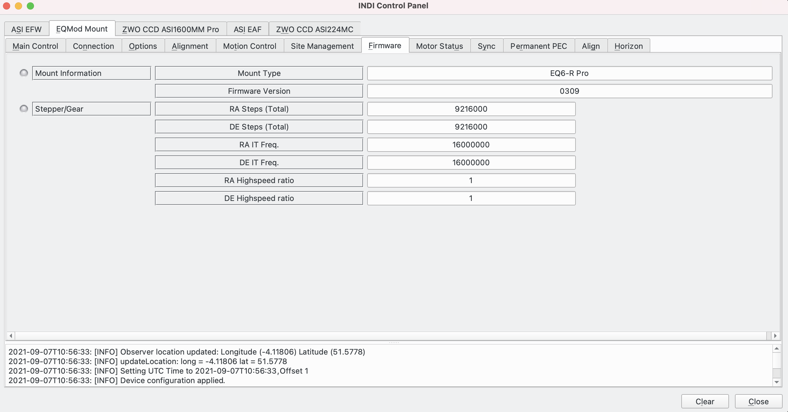
The Firmware tab displays information on the mount and firmware controller:
- Mount Information:
- Mount Type: The type of the mount.
- Firmware Version: Firmware version.
- Stepper/Gear: Displays information about the RA / Dec stepper motors and gearing.
Motor Status Tab
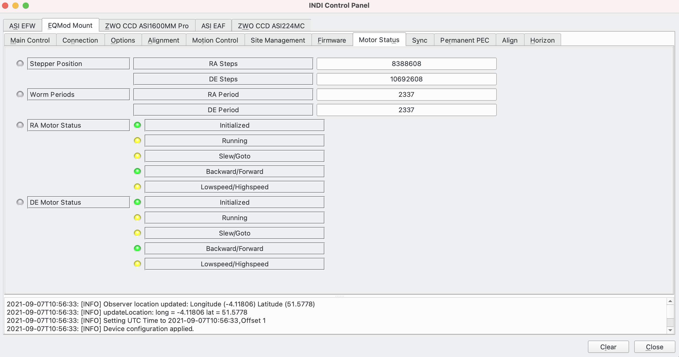
The Motor Status tab displays information about the mount stepper motors in RA and Dec:
- Stepper Position: Displays the position of the stepper motors.
- Worm Period: Displays the worm gear periods.
- Motor Status: Displays the status of the motors.
- Aux. Encoders: If the mount has auxilliary encoders then their position is displayed.
Sync Tab
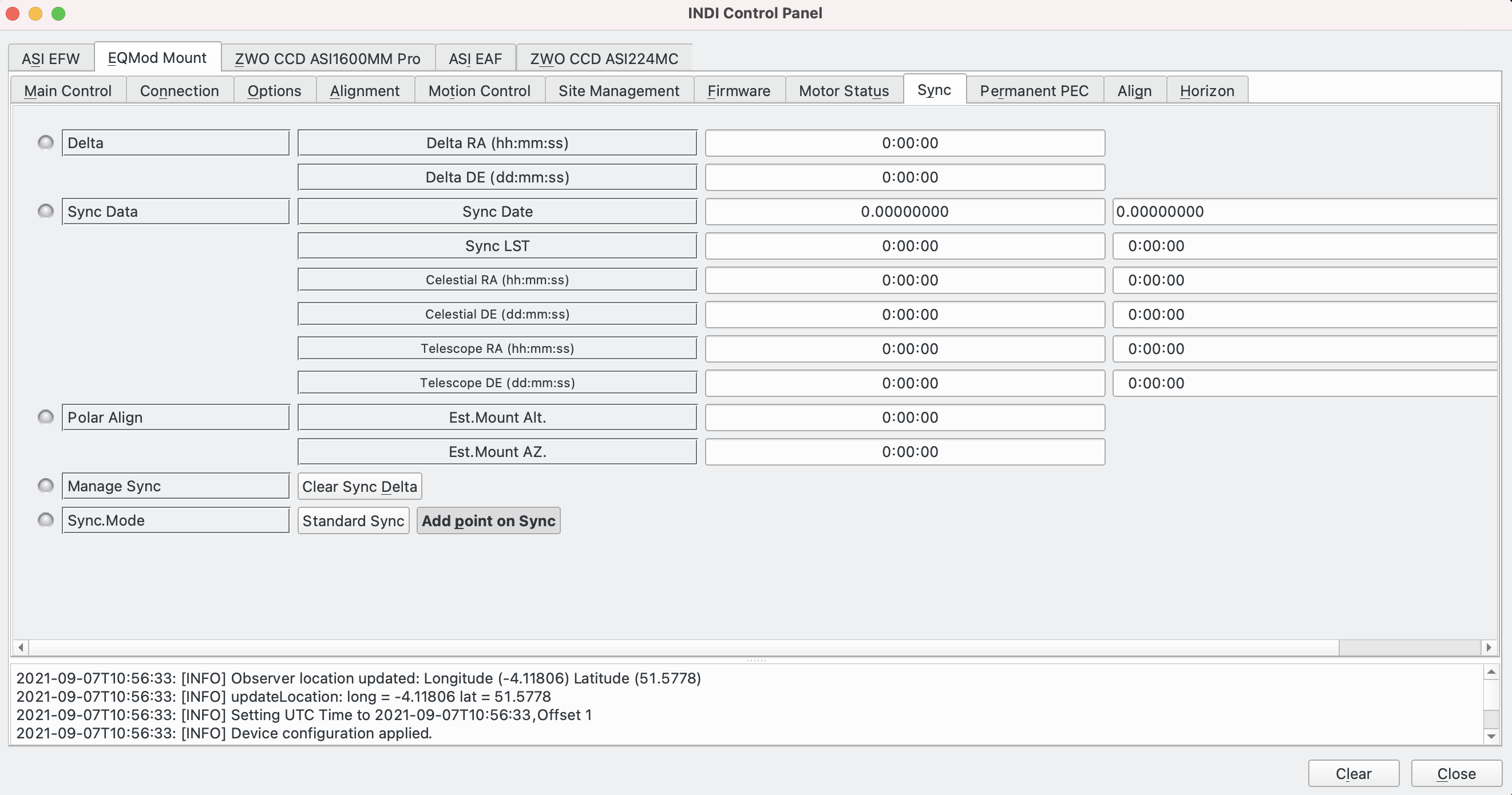
The Sync tab displays information about alignment points. As this repeats data on the Align tab, please see the Align tab section for more details.
Permanent PEC Tab
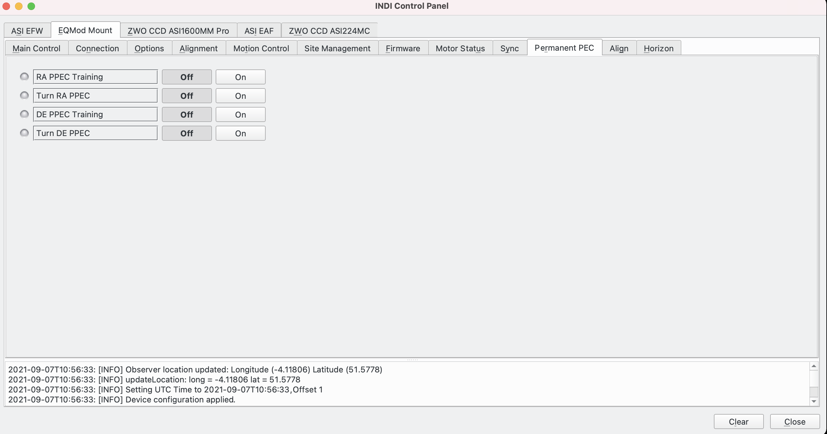
The Permanent PEC tab exposes the Permanent PEC (PPEC) functionality if it is supported by the mount:
- RA/DE PPEC training: Training can be enabled and disabled. PPEC training works the same way as with the mount handcontroller: guide on a star, engage PPEC training and the firmware will wait for the mount to pass the worm indexer and then record the resulting speeds in the EEPROM of the motor microcontroller as the worm travels through its cycle. The status is busy/yellow during training. When the worm has completed its cycle, the status of PPEC training becoming green.
- Turn RA/DE PPEC: PPEC can be turned on or off.
PPEC is normally only used on the RA worm.
PPEC is a complicated subject. INDI exposes the above mount functions but note that to effectively use PPEC requires many more steps and an understanding of how it works with your specific mount and what the constraints are (for example, to keep the stepper motor synchronised to the PPEC data). A good resource for more details on this topic can be found at The EQMOD Project.
Align Tab
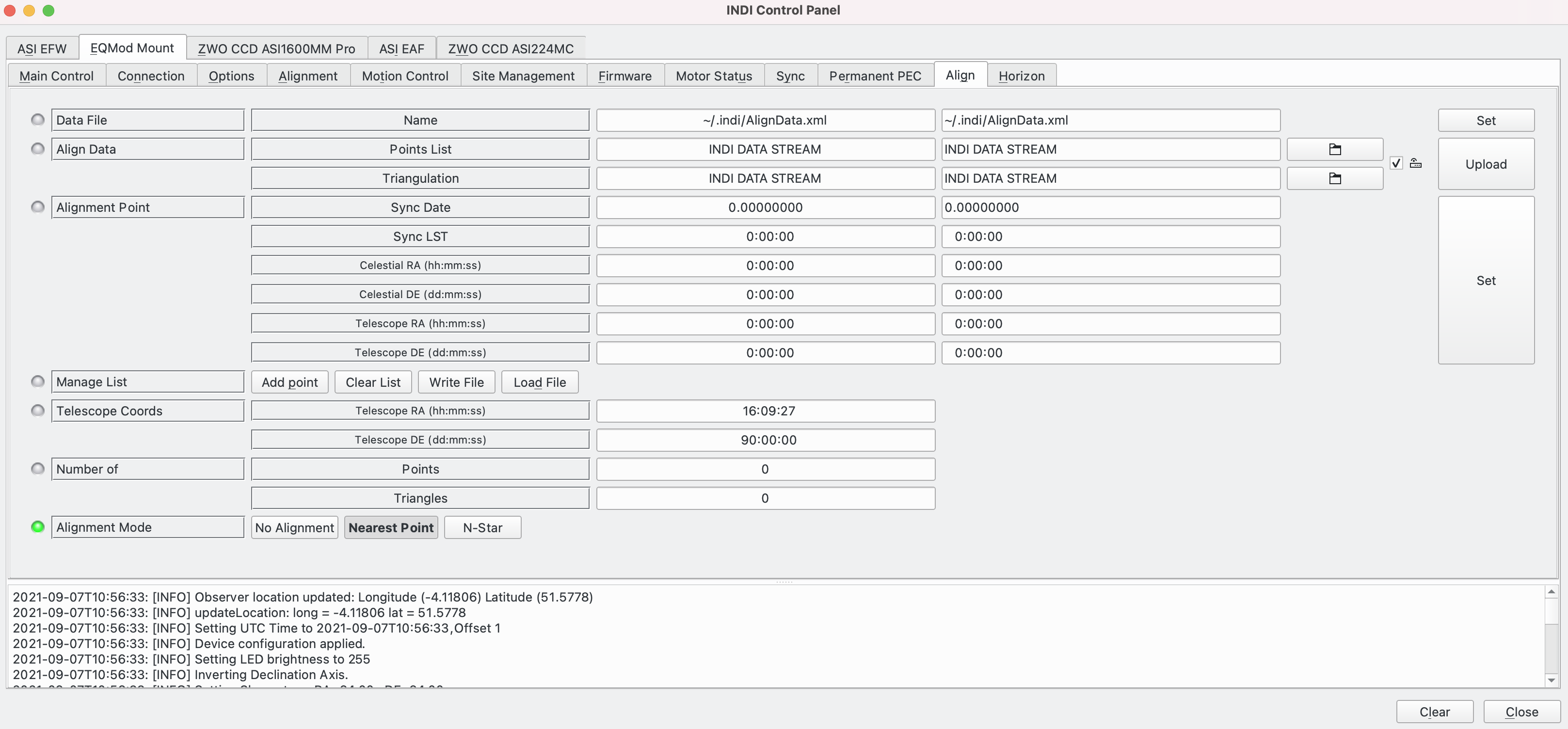
The Align tab displays information about the alignment of the mount:
- Data File: The file use for alignment data.
- Align Data: Set the alignment data on INDI DATA STREAM.
- Alignment Point: Holds data for the alignment point:
- Sync Date: The date the point was taken.
- Sync LST: Local Sidereal Time the point was taken.
- Celestial RA/DE: The celestial RA/Dec coordinates of the point.
- Telescope RA/DE: The telescope RA/Dec coordinates of the point.
- Manage List: Perform actions on the list of points:
- Add Point: Add a point to the list.
- Clear List: Remove all points from the list.
- Write File: Write the list of points to a file.
- Load File: Load a previously saved file of points.
- Telescope Coords: Current telescope RA/Dec coordinates.
- Number Of:
- Points: The number of alignment points in the list.
- Triangles: The number of triangles created from alignment Points.
- Alignment Mode:
- No Alignment: Do not use an alignment model.
- Nearest Point: Use the Nearest Point alignment model. When the mount is asked to perform a goto, the nearest alignment point to the requested goto position is used to calculate how to move the mount.
- N-Star: Use the N-Star alignment model. This is a more complicated alignment model that utilises all the alignment points in the list as effectively as it can calculate how to move the mount.
For background information on alignment models the EQMOD project has a useful document here.
N-Star alignment is the most accurate method of performing "gotos" standalone. When using plate solving, however, a very accurate goto is not required as plate solving refines every slew position iteratively to home in on the target. In this case it is better to use Nearest Point.
Horizon Tab
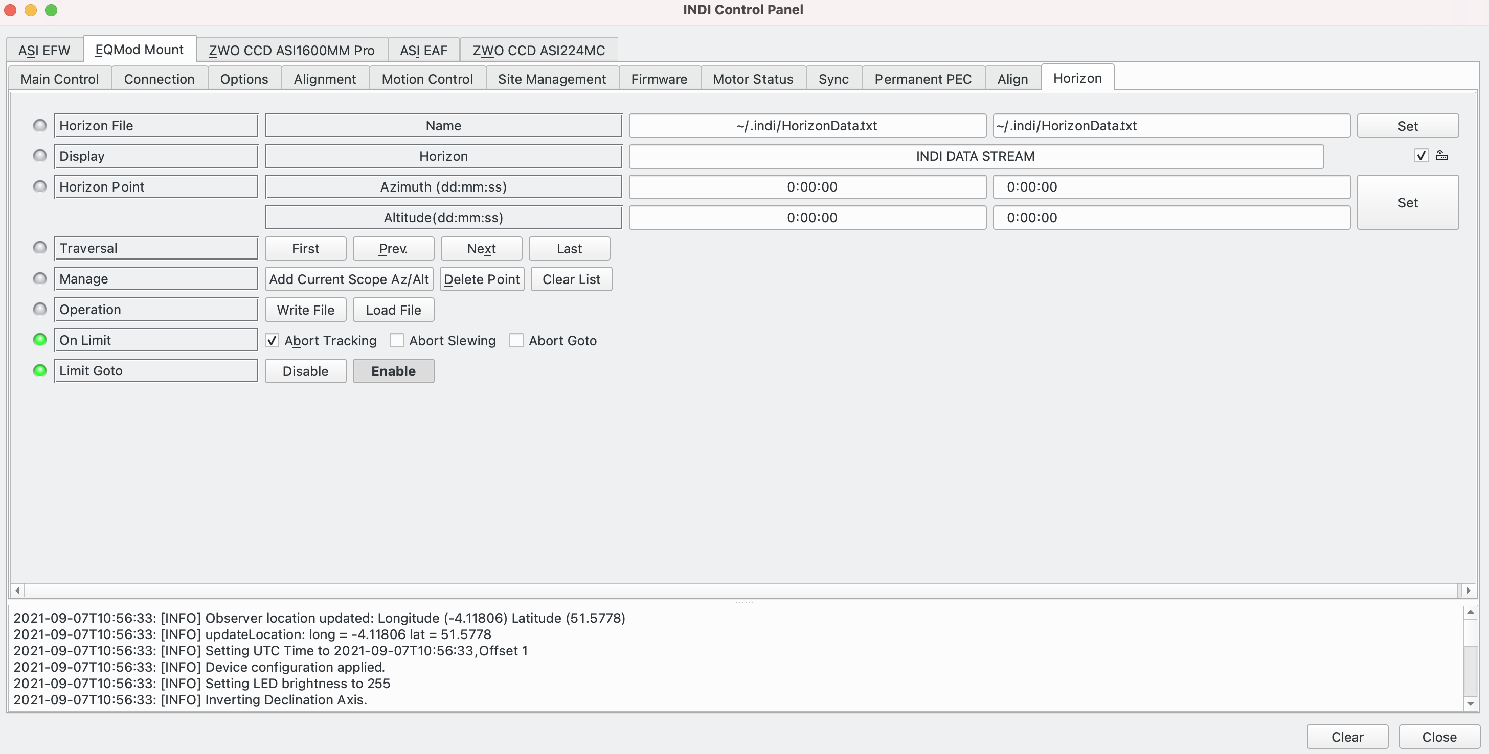
The Horizon tab displays and sets data associated with defining an artificial horizon for your observing location. To use, slew to the points along the horizon you want to set and hit the Add Current Scope Az/Alt button. The order of points is significant as Horizon uses a linear approximation between them. When you have finished hit the Write File button. The data is saved in a text file that can also be manually edited.
- Horizon File: The file used to store the data for the horizon being defined.
- Display: Put the horizon data on INDI DATA STREAM.
- Horizon Point: The Alt/Az coordinates of a point to define in the horizon file.
- Traversal: Allows display of previously defined horizon points:
- First: Displays the first point.
- Next. Displays the next point.
- Prev: Displays the previous point.
- Last: Displays the last point.
- Manage: Allows management of the list of horizon points:
- Add Current Scope Az/Alt: Add the current scope's position as a new horizon point.
- Delete Point. Delete the currently selected horizon point from the list.
- Clear List. Delete all points from the list.
- Operation: Manage the horizon points file.
- Write File: Write the file of horizon points.
- Load File: Load up a previously stored file of horizon points.
- On Limit: Actions to take during observing when the telescope reaches the horizon perimeter defined by the current list of horizon points.
- Abort Tracking: Stop tracking.
- Abort Slewing: Stop slewing.
- Abort Goto: Stop goto.
- Limit Goto: If enabled, limit the goto to the boundary of the horizon.
Issues
The current list of outstanding issues can be viewed at INDI's Github issues page. If you find an issue please report it on the Indilib forum and remember to include the logs (details on how to do this here).
Listing Details

After installing indi-bin, indi-eqmod and adding user to group dailout it is necessary to find the right connection to the mount.
Start the mount and align it, for testing it is enough to do it without a star. Take the handheld SynScan V4 and connect it to PC-USB
1) Use the INDI-server with the module SynScan - ready
2) By using PC-Mod on the handheld use the module EQMod for INDI-server - also ready
A nice stand alone tool is EQmod (apt-get install eqmodgui)
Submit review See all 1 reviews